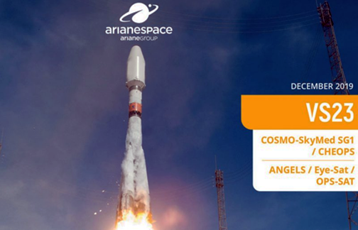
During final countdown operations for Flight VS23, the Soyuz launcher’s automated sequence was interrupted at 1 hour 25 minutes before liftoff.
As a result, the launch of the COSMO-SkyMed Second Generation, CHEOPS, OPS-SAT, EyeSat, ANGELS satellites – originally scheduled for December 17 – has been postponed.
The Soyuz launcher and its satellite payloads were placed in a fully safe standby mode.
The new target launch date will be announced as soon as possible.
The launch will take place via an Arianespace Soyuz rocket from Kourou, French Guiana (with co-passenger CHEOPS), European Space Agency‘s (ESA) 30 cm. high OPS-SAT smallsat flying lab is planned for injection into a circular, polar orbit at 515 km. altitude.
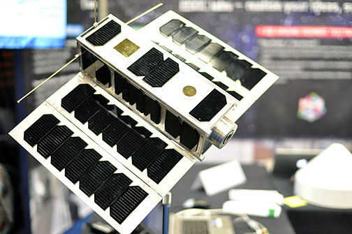
Photo of a replica of ESA’s OPS-SAT. The smallsat is made up of three standardized 10x10x10 cm. cubesat units with deployable solar panels on each side. Image is courtesy of ESA.
The smallsat will be controlled from the dedicated SMILE control room at ESOC. A flying laboratory, ESA’s OPS-SAT’s sole purpose is to test and validate improved mission control and on-board satellite systems, especially relevant when smallsats are able to fly with more powerful computers aboard them. OPS-SAT will pack a computer that is 10x more powerful than any previous or current ESA satellite.
The robustness of the basic satellite itself will give ESA flight control teams the confidence they need to upload and try out new, innovative control software submitted by experimenters; the satellite can be pushed to its limits but can always be recovered if something goes wrong. To manage these tasks, OPS-SAT combines off-the-shelf subsystems typically used with cubesats, the latest terrestrial microelectronics for the on-board computer and the experience ESA has gained in operating satellites for the last 40 years in keeping missions safe.

The SMILE lab – known more formally as the Special Mission Infrastructure Lab Environment – offers a flexible operations control area, a suite of small antennas and ESA’s expertise and know-how to support academia, business and start-ups in the area of mission operations. Photo is courtesy of ESA.
The result is an open, flying ‘laboratory’ that will be available for on-orbit demonstration of new control systems and software that would be too risky to trial on a ‘real’ satellite. More than 100 companies and institutions from 17 European countries have registered experimental proposals to fly on OPS-SAT.
The on-orbit laboratory will offer a range of resources, including processors, field-programmable gate arrays (FPGAs), cameras, and an attitude determination and control system, all of which experimenters will be able to exploit for demonstrating new mission and operations concepts.
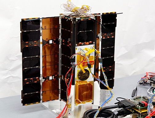
OPS-SAT during testing of its solar arrays at the Graz University of Technology, Austria.
Photo is courtesy of TU Graz.
The OPS-SAT architecture consists of two major parts. The first is the OPS-SAT ‘bus,’ which provides the necessary infrastructure to operate the second part, the payload. However, in this case, once the payload is running, it can take over control of the entire satellite, while the bus monitors and is ready to take control back at any moment.
The Payload
Processing Platform
The heart of the OPS-SAT satellite payload is the processing platform, which is responsible for providing a reconfigurable environment able to fulfil the objectives of each experiment. The processing platform runs Linux, as the operating system consists of a flexible and reconfigurable framework, featuring sophisticated processing capabilities, interfaces, memory integrity and reconfigurable logic.
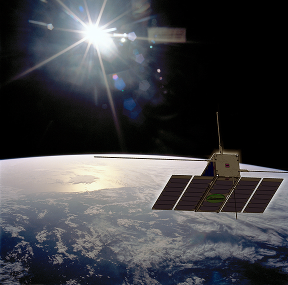
Artistic rendition of ESA’s OP-SAT on-orbit.
Image is courtesy of ESA.
The platform consists of an ‘Altera Cyclone V SoC’ with an ARM dual-core Cortex-A9 MPCore and a Cyclone V FPGA. OPS-SAT experimenters will provide bootable images for this processing platform. These images will undergo certain pre-checks before loading to the spacecraft. Power consumption and temperature of the processing core will also be monitored by the on-board computer to provide additional safety mechanisms.
Fine Attitude Determination Control System (ADCS) + GPS Receiver
An integrated, fine ADCS will provide the experimenters with access to sensors and actuators as well as integrated attitude control functionality and consists of gyros, accelerometers, magnetometers, reaction wheels, three magnetorquers and a Star Tracker. A GPS module is also provided in order for experimenters to have access to positioning data and time information.
S-Band Transponder
For high data-rate communications, a CCSDS-compatible S-band communication link, acting as the main link for data communications and TM/TC with ESA ground stations, is provided. This comms link will provide uplink speeds of up to 256 kbit/s and downlink speeds of up to 1 Mbit/s. The S-band link will be used to upload experimenter’s’ software and download results of on-board experiments.
X-Band Transmitter
An X-band transmitter with high data-rate communications of up to 50 Mbit/s.
Camera
A high-resolution camera which can provide a ground resolution of up to 80m x 80m per pixel.
Optical Uplink
An optical receiver will be provided that can receive commands from a laser ranging station on Earth. An uplink rate of 2 kbps is expected.
Software Defined Radio (SDR)
A software-defined radio front end will be provided, connected to one of the pair of dipoles in the UHF antenna. The results of this experiment will be made available on the processing core for further processing by experimenters, for example, providing a flying spectrum analyzer.
Interfaces
Experimenters will be able to communicate with their flying experiments in various ways, ranging from offline file transfer only, to receiving and sending space packets in real-time with a brand new CCSDS protocol (MO services) over the internet.
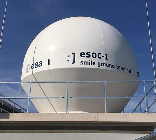
The ESOC-1 antenna is a 3.7 meter single parabolic reflector – a key part of ESA’s SMILE mini-mission control and validation center.
Photo is courtesy of ESA.
Project status
SMILE!, ESA’s mini-mission control facilities, are now open to the public
Funding
The project is funded by the ESA General Support Technology Program. This project kicked off on February 4, 2015, with the prime contractor, the Technische Universität Graz, and subcontractors.
